AstroCAN Con Slots Plus
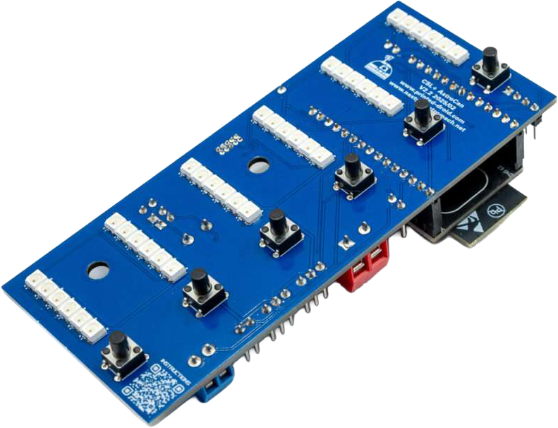

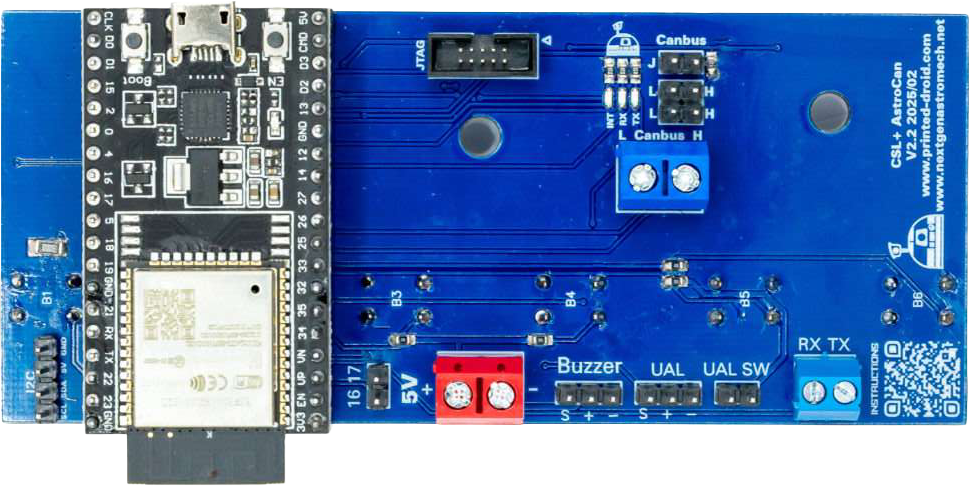
I2C Port for connecting other dome modules.
reserved for future use
Important: 5V ONLY! Otherwise you will damage your board.
!Check polarity!
Pin Header for small buzzer or other acoustic feedback device.
Connect your passive UAL LED Module.
Connect your UAL switch to indicate, when to start upload sequence animation.
Interface for communication with MarcDuino boards.
CAN-Bus Terminator
Can-Bus pin header
Can-Bus Screw Terminal. Same as CAN-Bus Pin Header.
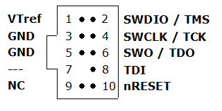
Debugging Interface, Developers only.
Press to restart module
Connector for flashing and configuring your device.
Hold for 3s to start ESP-Now-Pairing (see documentation for details)
ESP32 Dev Kit V4
Do not cover with metallic case etc.
| Hotspot | Function | Description |
|---|---|---|
| 1 | I2C Connector | I2C Port for connecting other dome modules. |
| 2 | Free GPIOs | reserved for future use |
| 3 | Power Supply, 5.0V | Power Supply, 5.0V. Important: 5V ONLY! Otherwise you will damage your board. |
| 4 | Buzzer | Pin Header for small buzzer or other acoustic feedback device. |
| 5 | UAL-Connector | Connect your passive UAL LED Module. |
| 6 | UAL Switch Connector | Connect your UAL switch to indicate, when to start upload sequence animation. |
| 7 | Serial Connector | In DOME-Mode: – Connect RXD to MarcDuino MP3 pin – Connect TXD to MarcDuino Master RX In BODY-Mode: |
| 8 | CAN-Bus Terminator | CAN-Bus Terminator. See CAN Termination for Details |
| 9 | CAN-Bus | CAN-Bus Pin Header |
| 10 | CAN-Bus | Can-Bus Screw Terminal. Same as CAN-Bus Pin Header |
| 11 | JTAG-Connector | Debugging Interface, Developers only |
| 12 | Reset Button | Press to restart module |
| 13 | USB-Connector | Connector for flashing and configuring your device |
| 14 | Pair / Boot Button | Hold for 3s to start ESP-Now-Pairing. Bridge module has to be connected to AstroCAN Shield / AstroCAN Brain via CAN-Bus to get paring information! |
| 15 | ESP32 Dev Kit V4 | ESP32 Dev Kit V4 (in case you have to replace it…) |
| 16 | WIFI/NOW Antenna | Do not cover with metallic case etc. |
Use serial terminal to connect via USB (see above) to AstroCAN-Module. If your browser supports “Web Serial”, you also can use the terminal available in the Firmware section. Communication speed ist 115200 baud. The following commands are available for configuration and management.
Note: The light configuration parameters differ from the common AstroCAN syntax. This is due to compatibility to the Arduino Nano board with less memory.
CS – CSL
UA – UAL
CO – Base Color, 3 separate Values for R/G/B, 0-255 each
BR – Brightness, 1 Value 0-255
AN – Animation Number, 1 Value 0-255
AS – Animation Speed, 1 Value 0 – 65535
EF – Effect, 1 Value 0-255
ES – Effect Speed, 1 Value 0-65535
/CS/BR/50 – CSL, Brightness 50 (0-255 for AstroPixels)
/UA/CO/255/0/0 – UAL, Base Color Red (R/G/B)
:
Use serial terminal to connect via USB (see above) to AstroCAN-Module. If your browser supports “Web Serial”, you also can use the terminal available in the Firmware section. Communication speed ist 115200 baud. The following commands are available for configuration and management:
| Command | Parameters | Description | Example |
|---|---|---|---|
| /HELP | – | shows usage | /HELP |
| /SETTINGS | – | shows all settings stored in EEPROM | /SETTINGS |
| /WIFIAPSSID | AP SSID | sets the access point SSID | /WIFIAPSSID R2TOCH |
| /WIFIAPPASSWORD | AP Password | sets the access point password | /WIFIAPPASSWORD R2TOUCH123 |
| /WIFISSID | WIFI SSID | sets the WLAN SSID | /WIFISSID HOMELAN |
| /WIFIPASSWORD | WIFI Password | sets the WLAN Password | //WIFIPASSWORD HOMELAN123 |
| /PAIR | – | auto pair module with ESP-NOW peer (connect both modules to CAN for pairing)
Pairing mode depends on Dome jumper. When in dome mode, it looks for brain/shield module. When in body mode, it looks for bridge module. | /PAIR |
| /NOWLMK | 16 byte key | sets the local master key for ESP-NOW communication. See -> ESP-NOW encryption for details. | /NOWLMK 0123456789ABCDEF |
| /NOWPMK | 16 byte key | sets the primary master key for ESP-NOW communication. See -> ESP-NOW encryption for details. | /NOWPMK 0123456789ABCDEF |
| /NOWCHANNEL | Channel | sets the ESP-NOW channel number | /NOWCHANNEL 5 |
| /NOWSETPEER | MAC Address in xx:xx:xx:xx:xx:xx format | set ESP-NOW communication peer MAC address | /NOWSETPEER 01:23:45:67:89:AB |
| /NOWCLEARPEERS | – | clear all ESP-NOW communication peers | /NOWCLEARPEERS |
| /NOWLISTPEERS | – | list all ESP-NOW communication peers | /NOWLISTPEERS |
| /RESTART | – | restart module | /RESTART |
| /FACTORY | – | set factory settings and restart module. All EEPROM settings will also be set to default. | /FACTORY |
| /ACTIVATE | CAN|CAN1|CAN2|NOW|WIFI|ENC | acticate CAN-/NOW-/WIFI-Functionality or ESP-NOW encryption. CAN1/CAN2 only available on Dual-CAN-Boards. | /ACTIVATE CAN |
| /DEACTIVATE | CAN|CAN1|CAN2|NOW|WIFI|ENC | deacticate CAN-/NOW-/WIFI-Functionality or ESP-NOW encryption. CAN1/CAN2 only available on Dual-CAN-Boards. | /DEACTIVATE CAN |
| /NOWSET… | MAC Address in xx:xx:xx:xx:xx:xx format | set ESP-NOW module peer address | /NOWSETDOME 01:23:45:67:89:AB |
| /WIFIAPIP | IP-Address in xxx.xxx.xxx.xxx format | set Access Point Local IP | /WIFIAPPIP 192.168.10.1 |
| /WIFIAPGW | IP-Address in xxx.xxx.xxx.xxx format | set Access Point Gateway | /WIFIAPPGW 192.168.10.0 |
| /WIFIAPSN | IP-Address in xxx.xxx.xxx.xxx format | set Access Point Subnet Mask | /WIFIAPPSN 255.255.255.0 |
| /SETBUTTON | nr color_red color_green color_blue primary_command (secondary_command) | stores command “command” in button “nr”. Sets color to “color_red” “color_green” “color_blue” | /SETBUTTON 1 0 0 255 :OP01 :CL01 |
| /CLEARBUTTON | nr | removes stored command and color from button “nr” | /CLEARBUTTON 1 |
| /SETCOMMAND | nr primary_command (secondary_command) | stores command “command” in button “nr”. Does not change color settings. | /SETCOMMAND :OP01 :CL01 |
Use serial terminal to connect via USB (see above) to AstroCAN-Module. Communication speed ist 115200 baud. The following settings can be configured (see command set above):
| Setting | Description | Example | Config Command |
|---|---|---|---|
| MAC | MAC Address of ESP32 | 12:34:56:78:9A:BC | fix, not configurable |
| AP_SSID | Name of the access point network, the AstroCAN module opens up to get connected by apps like R2-Touch | R2TOUCH | /WIFIAPSSID |
| AP_Password | Password of the Access point network. | R2TOUCH123 | /WIFIAPPASSWORD |
| WLAN_SSID | Name of the WLAN the AstroCAN module can connect to, to be controlled by other systems within that network | HOMELAN | /WIFISSID |
| WLAN_Password | Password of the WLAN the AstroCAN module can connect to. | HOMELAN123 | /WIFIPASSWORD |
| NOW_PMK | ESP-NOW encryption parameter: Primary Master Key. See -> ESP-NOW encryption for details.
Only change, if you exactly know, what you are doing! | 0123456789ABCDEF | /NOWPMK |
| NOW_LMK | ESP-NOW encryption parameter: Local Master Key. See -> ESP-NOW encryption for details.
Only change, if you exactly know, what you are doing! | 0123456789ABCDEF | /NOWLMK |
| NOW_Channel | WIFI channel to be used for ESP-NOW communication. All ESP-NOW peers have to communicate over the same channel number | 5 | /NOWCHANNEL |
| CAN1_Active | Shows, if main CAN bus is active | true – activated false – deactivated | /ACTIVATE CAN /ACTIVATE CAN1 /DEACTIVATE CAN |
| CAN2_Active | Shows, if secondary CAN bus is active | true – activated false – deactivated | /ACTIVATE CAN2 /DEACTIVATE CAN2 |
| NOW_Active | Shows, if ESP-NOW is active | true – activated false – deactivated | /ACTIVATE NOW /DEACTIVATE NOW |
| WIFI_Active | Shows, if WIFI is active | true – activated false – deactivated | /ACTIVATE WIFI /DEACTIVATE WIFI or WIFI jumper |
| NOW_Encryption | Shows, if ESP-NOW encryption is active. See -> ESP-NOW encryption for details. | true – activated false – deactivated | /ACTIVATE ENC /DEACTIVATE ENC |
| WIFI_Active | Shows, if WIFI is active | true – activated false – deactivated | WIFI jumper set: WIFI activated WIFI jumper removed: WIFI deactivated |
| AP_IP | Access Point Local IP | 192.168.10.1 | /WIFIAPIP |
| AP_GW | Access Point Gateway | 192.168.10.0 | WIFIAPGW |
| AP_SN | Access Point Subnet Mask | 255.255.255.0 | /WIFIAPSN |
| CAN-ID | CAN Identifier of Module | 0x7E0 | fixed |
| Peers | Description | Example | Configuration |
| CAN-Resp-ID | CAN Response Identifier of Module | 0x7E8 | fixed |
| Stored Peers | MAC-Adresses of ESP-NOW communication partners | 12:34:56:78:9A:BC | /NOWSET… |
| Live Peers on Bus | MAC-Adresses of AstroCAN modules found on CAN bus | 12:34:56:78:9A:BC | conditional |
The CSL+ AstroCan is the logical addition to the AstroCan system. Together with the other AstroCan modules, it integrates seamlessly into the system, with the lights controlled via sequences, offering much more than all other DPL versions currently on the market.
Additionally, it provides six extra input options for various functions.
Just add it to the CAN-Bus and Power. See Tech FAQ for additional information.
To install most recent firmware V2.5.9 connect the AstroCAN module via USB to your computer and click on “Connect” button.
Attention 1: When upgrading one module to V2.x, you have to upgrade ALL other AstroCAN-Modules to V2.x!
Attention 2: Read HowTo – Upgrade to V2.5 before upgrading!