Connectors
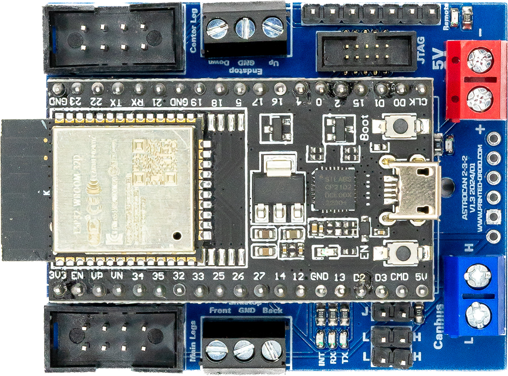
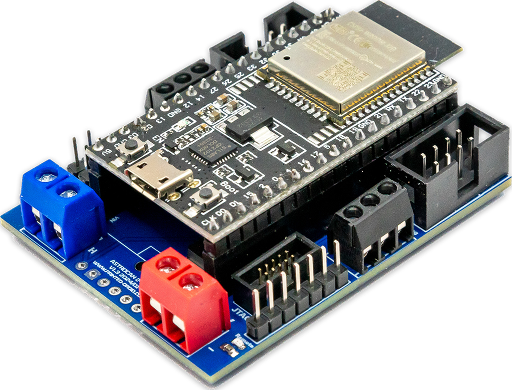
Connector Motor Driver Main Legs
Connector for IBT2 Motor Driver (or similar). See pinout below.
Connector Motor Driver Center Leg
Connector for IBT2 Motor Driver (or similar). See pinout below.
Pin Header Endstops Main Leg
Pin header for end stop Main Legs (Front/Back), Low Active.
I2C Connector
I2C Port for connecting other dome modules.
Pin Header Endstops Center Leg
Pin header for end stop Main Legs (Up/Down), Low Active.
CAN-Bus
Can-Bus pin header
CAN-Bus Terminator
CAN-Bus Terminator
CAN-Bus
Can-Bus Screw Terminal. Same as CAN-Bus Pin Header.
AstroBus
6-pin connector for specific module mounts
Power Supply
Important: 5V ONLY! Otherwise you will damage your board.
!Check polarity!
USB-Connector
Connector for flashing and configuring your device.
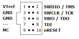
JTAG-Connector
Debugging Interface, Developers only.
ESP32 Dev Kit V4
ESP32 Dev Kit V4
Pair / Boot Button
Hold for 3s to start ESP-Now-Pairing (see documentation for details)
Reset Button
Press to restart module
WIFI/NOW-Antenna
Do not cover with metallic case etc.
Connector 4-Channel Remote Control
Connector for a 4-Channel Remote Control. See original Troy Flynn documentation for Details.
| Hotspot | Function | Description |
|---|---|---|
| 1 | Dome Jumper | Set jumper, when bridge is placed in dome and receives commands from the body. |
| 2 | WIFI Jumper | Set jumper, if you like to control your dome mechanisms with the R2-Touch App. Only one module in your droid should have this jumper set. |
| 3 | Free GPIOs | reserved for future use |
| 4 | I2C Connector | I2C Port for connecting other dome modules. |
| 5 | Serial Connector | In DOME-Mode: – Connect RXD to MarcDuino MP3 pin – Connect TXD to MarcDuino Master RX In BODY-Mode: |
| 6 | CAN-Bus | CAN-Bus Pin Header |
| 7 | CAN-Bus Terminator | CAN-Bus Terminator. See CAN Termination for Details |
| 8 | CAN-Bus | Can-Bus Screw Terminal. Same as CAN-Bus Pin Header |
| 9 | AstroBus | 6-pin connector for specific module mounts |
| 10 | Power Supply, 5.0V | Power Supply, 5.0V. Important: 5V ONLY! Otherwise you will damage your board. |
| 11 | USB-Connector | Connector for flashing and configuring your device |
| 12 | JTAG-Connector | Debugging Interface, Developers only |
| 13 | ESP32 Dev Kit V4 | ESP32 Dev Kit V4 (in case you have to replace it…) |
| 14 | Pair / Boot Button | Hold for 3s to start ESP-Now-Pairing. Bridge module has to be connected to AstroCAN Shield / AstroCAN Brain via CAN-Bus to get paring information! |
| 15 | Reset Button | Press to restart module |
JTAG
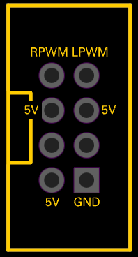
Motor Driver Pinout
Pin compatible to IBT-2 Motor Driver.
AstroBus (TOP VIEW!)
| 6 | 5 | 4 | 3 | 2 | 1 |
|---|---|---|---|---|---|
| +5V | GND | n/c | CANL | CANH | n/c |
Commands
Use serial terminal to connect via USB (see above) to AstroCAN-Module. If your browser supports “Web Serial”, you also can use the terminal available in the Firmware section. Communication speed ist 115200 baud. The following commands are available for configuration and management:
| Command | Parameters | Description | Example |
|---|---|---|---|
| /HELP | – | shows usage | /HELP |
| /SETTINGS | – | shows all settings stored in EEPROM | /SETTINGS |
| /WIFIAPSSID | AP SSID | sets the access point SSID | /WIFIAPSSID R2TOCH |
| /WIFIAPPASSWORD | AP Password | sets the access point password | /WIFIAPPASSWORD R2TOUCH123 |
| /WIFISSID | WIFI SSID | sets the WLAN SSID | /WIFISSID HOMELAN |
| /WIFIPASSWORD | WIFI Password | sets the WLAN Password | //WIFIPASSWORD HOMELAN123 |
| /PAIR | – | auto pair module with ESP-NOW peer (connect both modules to CAN for pairing)
Pairing mode depends on Dome jumper. When in dome mode, it looks for brain/shield module. When in body mode, it looks for bridge module. | /PAIR |
| /NOWLMK | 16 byte key | sets the local master key for ESP-NOW communication. See -> ESP-NOW encryption for details. | /NOWLMK 0123456789ABCDEF |
| /NOWPMK | 16 byte key | sets the primary master key for ESP-NOW communication. See -> ESP-NOW encryption for details. | /NOWPMK 0123456789ABCDEF |
| /NOWCHANNEL | Channel | sets the ESP-NOW channel number | /NOWCHANNEL 5 |
| /NOWSETPEER | MAC Address in xx:xx:xx:xx:xx:xx format | set ESP-NOW communication peer MAC address | /NOWSETPEER 01:23:45:67:89:AB |
| /NOWCLEARPEERS | – | clear all ESP-NOW communication peers | /NOWCLEARPEERS |
| /NOWLISTPEERS | – | list all ESP-NOW communication peers | /NOWLISTPEERS |
| /RESTART | – | restart module | /RESTART |
| /FACTORY | – | set factory settings and restart module. All EEPROM settings will also be set to default. | /FACTORY |
| /ACTIVATE | CAN|CAN1|CAN2|NOW|WIFI|ENC | acticate CAN-/NOW-/WIFI-Functionality or ESP-NOW encryption. CAN1/CAN2 only available on Dual-CAN-Boards. | /ACTIVATE CAN |
| /DEACTIVATE | CAN|CAN1|CAN2|NOW|WIFI|ENC | deacticate CAN-/NOW-/WIFI-Functionality or ESP-NOW encryption. CAN1/CAN2 only available on Dual-CAN-Boards. | /DEACTIVATE CAN |
| /NOWSETBRAIN | MAC Address in xx:xx:xx:xx:xx:xx format | set ESP-NOW brain peer address | /NOWSETBRAIN 01:23:45:67:89:AB |
| /232 | [2|3|4] | 232 positions: 2 – Two Legs, straight 3- Three Legs 4- Three Legs, straigth | /232 2 |
| /MOVE | [UP|DOWN|FRONT|BACK] speed time | move center motor or main legs at “speed” (im percent) for “time” (in milliseconds) | /MOVE UP 100 2000
HANDLE WITH CARE, DROID MIGHT BECOME INSTABLE! |
| /REMOTE | [0|1] | allow 4-channel remote control for 232 (security risk!) | /REMOTE 1 |
Settings
Use serial terminal to connect via USB (see above) to AstroCAN-Module. Communication speed ist 115200 baud. The following settings can be configured (see command set above):
| Setting | Description | Example | Config Command |
|---|---|---|---|
| MAC | MAC Address of ESP32 | 12:34:56:78:9A:BC | fix, not configurable |
| AP_SSID | Name of the access point network, the AstroCAN module opens up to get connected by apps like R2-Touch | R2TOUCH | /WIFIAPSSID |
| AP_Password | Password of the Access point network. | R2TOUCH123 | /WIFIAPPASSWORD |
| WLAN_SSID | Name of the WLAN the AstroCAN module can connect to, to be controlled by other systems within that network | HOMELAN | /WIFISSID |
| WLAN_Password | Password of the WLAN the AstroCAN module can connect to. | HOMELAN123 | /WIFIPASSWORD |
| NOW_PMK | ESP-NOW encryption parameter: Primary Master Key. See -> ESP-NOW encryption for details.
Only change, if you exactly know, what you are doing! | 0123456789ABCDEF | /NOWPMK |
| NOW_LMK | ESP-NOW encryption parameter: Local Master Key. See -> ESP-NOW encryption for details.
Only change, if you exactly know, what you are doing! | 0123456789ABCDEF | /NOWLMK |
| NOW_Channel | WIFI channel to be used for ESP-NOW communication. All ESP-NOW peers have to communicate over the same channel number | 5 | /NOWCHANNEL |
| CAN1_Active | Shows, if main CAN bus is active | true – activated false – deactivated | /ACTIVATE CAN /ACTIVATE CAN1 /DEACTIVATE CAN |
| CAN2_Active | Shows, if secondary CAN bus is active | true – activated false – deactivated | /ACTIVATE CAN2 /DEACTIVATE CAN2 |
| NOW_Active | Shows, if ESP-NOW is active | true – activated false – deactivated | /ACTIVATE NOW /DEACTIVATE NOW |
| WIFI_Active | Shows, if WIFI is active | true – activated false – deactivated | /ACTIVATE WIFI /DEACTIVATE WIFI or WIFI jumper |
| NOW_Encryption | Shows, if ESP-NOW encryption is active. See -> ESP-NOW encryption for details. | true – activated false – deactivated | /ACTIVATE ENC /DEACTIVATE ENC |
| 232_Remote | allow 4-channel remote control for 232 (security risk!) | 1 | /REMOTE |
| Jumpers | Description | Example | Configuration |
| Dome/Body Mode | DOME jumper set: Dome Mode DOME jumper removed: Body Mode | ||
| WIFI_Active | Shows, if WIFI is active | true – activated false – deactivated | WIFI jumper set: WIFI activated WIFI jumper removed: WIFI deactivated |
| Peers | Description | Example | Configuration |
| Peer | MAC-Adress of ESP-NOW communication partner, not used in bridge module | 12:34:56:78:9A:BC | /NOWSETPEER |
| Dome | MAC-Adress of ESP-NOW communication partner place in dome | 12:34:56:78:9A:BC | /NOWSETDOME |
| Body | MAC-Adress of ESP-NOW communication partner place in body | 12:34:56:78:9A:BC | /NOWSETBODY |
F.A.Q – AstroCAN 232
What is it?
This is a module compatible with Troy Flynn’s 232 solution. The mechanics and the motor drivers remain identical, only the AT-Mega is exchanged for the new module based on ESP32 including CAN.
Features
- ESP-NOW Wireless Module<->Brain Comm (serial, Canbus, I2C)
- CAN-Bus for upcoming CAN-enabled Astromech Devices
- JTAG-Live Debugging
- Status Leds for serial & CanBus transmission
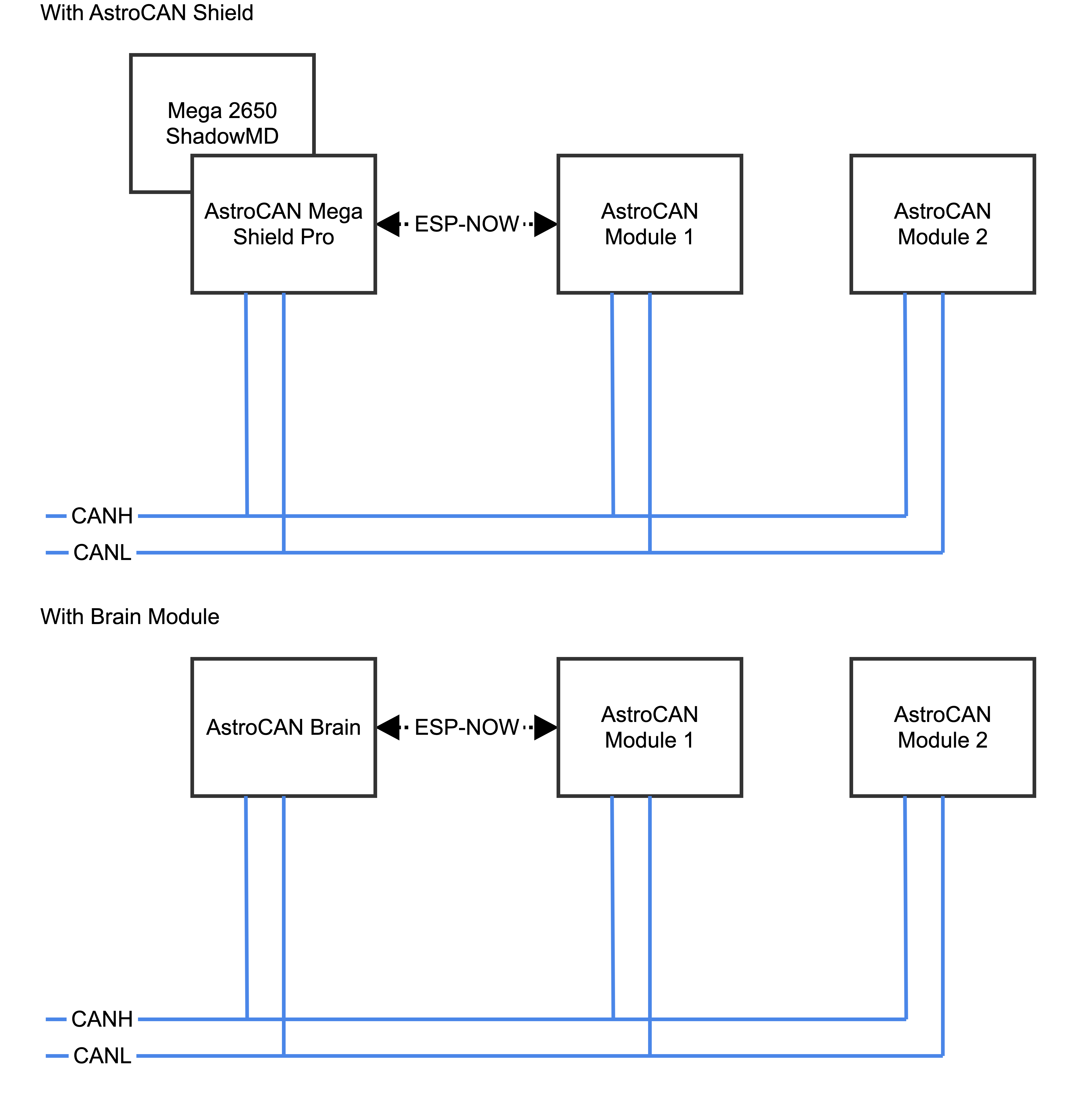
The ESPNow system is exclusively utilized for connecting the AstroCAN modules. It efficiently transfers all CAN signals and one serial interface between the dome and body through ESPNow.
All modules adhere to a standardized size and possess an identical “Astrobus” interface. This uniformity enables secure mounting onto the electronics board without the need for extensive wiring. However, the use of the Astrobus is not mandatory, and traditional free-floating wiring can be used if preferred.
Best Practice – Wiring
Firmware Installer
To install most recent firmware V2.0.0 connect the AstroCAN module via USB to your computer and click on “Connect” button.
Attention: When upgrading one module to V2.x, you have to upgrade ALL other AstroCAN-Modules to V2.x!
Firmware Download
ESP-Tool-Upgrade
The firmware has been compiled using esptool, ready to flash to offset 0x00.
Firmware AstroCAN-232 download
OTA-Upgrade (Firmware 2.5 and greater)
Read HowTo – Upgrade to V2.5 before upgrading!
Revision History
Version 2.5.6 (03. August 2025)
Bugfixes
- –
Features
- All new upgrade including OTA update with WebServer
Attention: When upgrading one module to V2.x, you have to upgrade ALL other AstroCAN-Modules to V2.x!
Version 2.0.0 (27. January 2025)
Bugfixes
- Invalid member initialization
Features
- based on updated AstroCAN Toolkit
- Support for MCP2517/MCP2518/MCSP2818FD CAN Protocols
Attention: When upgrading one module to V2.x, you have to upgrade ALL other AstroCAN-Modules to V2.x!
Version 1.5.4 (05. January 2025)
Bugfixes
- typos
Features
- added remote control handling
- updated to recent AstroCAN toolset

