AstroCAN AutoDome
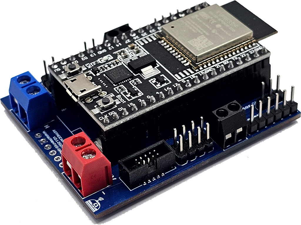

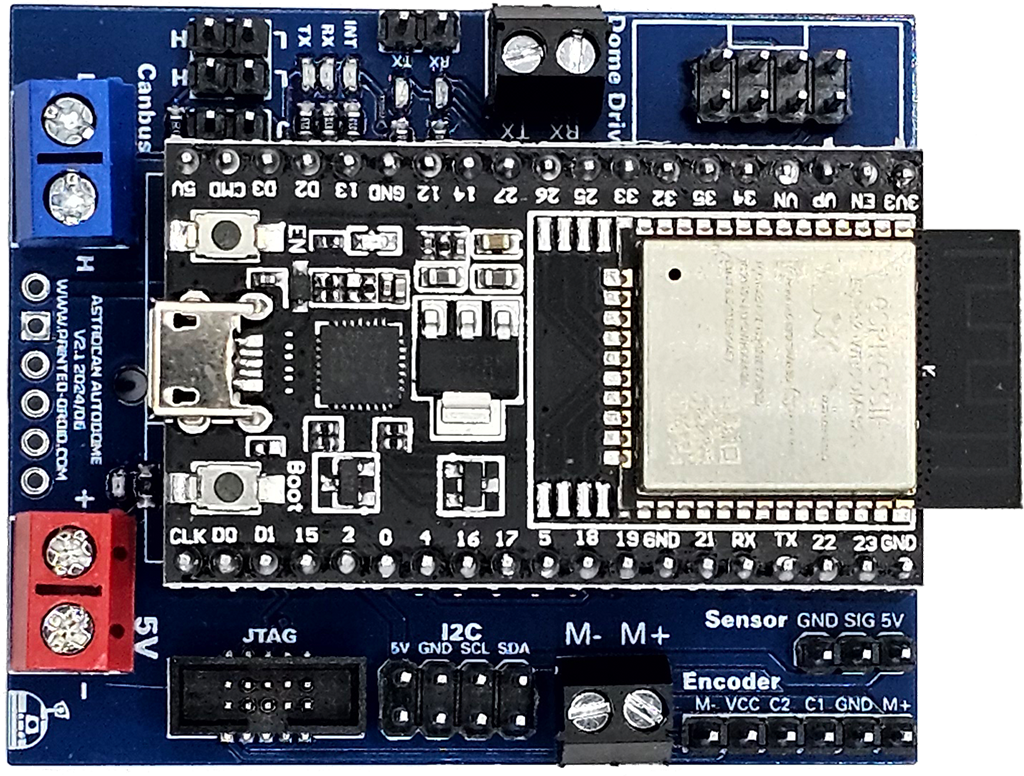
Can-Bus Screw Terminal. Same as CAN-Bus Pin Header.
6-pin connector for specific module mounts
Important: 5V ONLY! Otherwise you will damage your board.
!Check polarity!
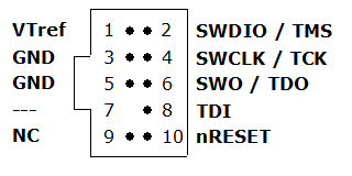
Debugging Interface, Developers only.
I2C Port for connecting other dome modules.
See wiring instruction for details. Do not just connect constant voltage!!!
Pin header to connect your Dome Motor with built-in encoder.
Connect your position sensor here. Can be a microswitch, an optical switch or a hall sensor. Recommended to install at center position.
ESP32 Dev Kit V4
Do not cover with metallic case etc.
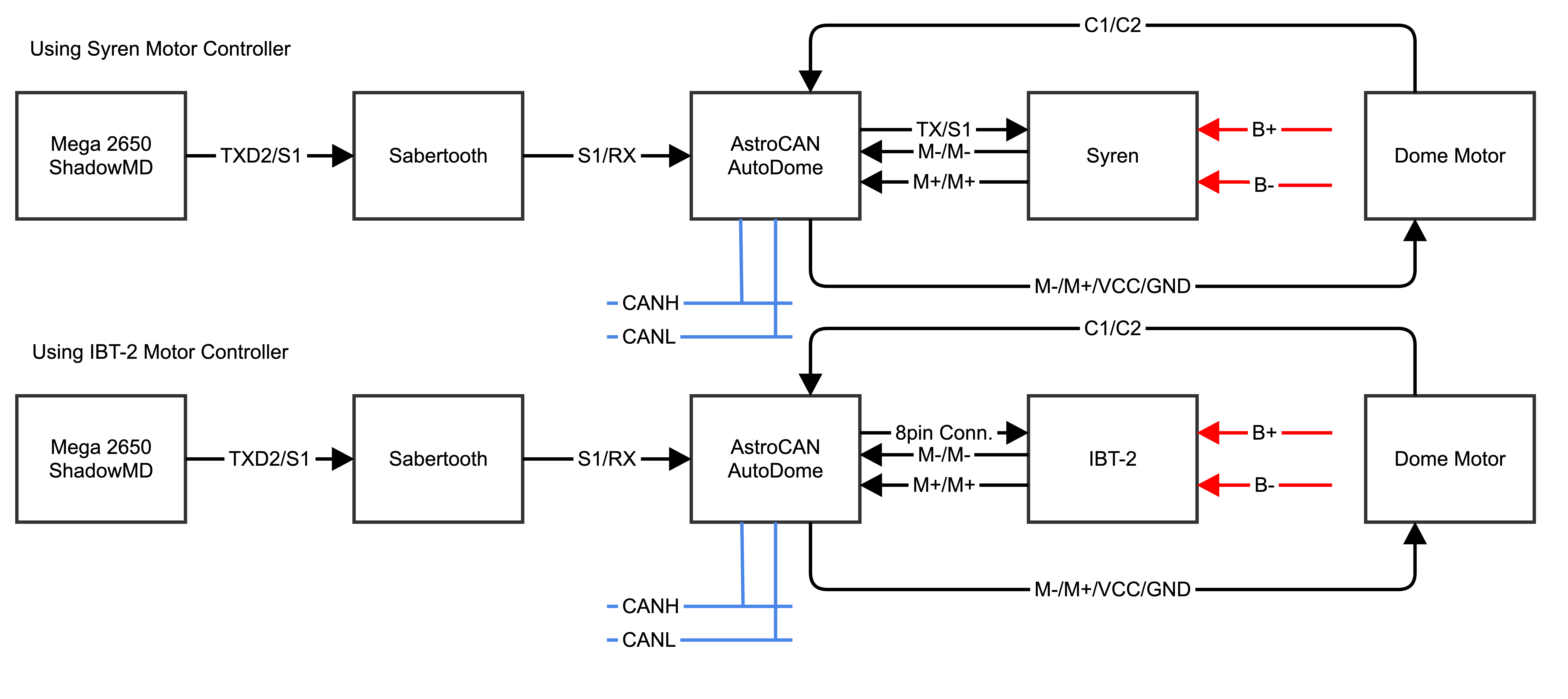
Connector for IBT2 Motor Driver (or similar). See pinout below.
Serial communication from Shadow to Syren. See wiring below.
Interface for communication with serial monitor for PID tuning.
Can-Bus pin header
CAN-Bus Terminator
Press to restart module
Connector for flashing and configuring your device.
Hold for 3s to start ESP-Now-Pairing (see documentation for details)
| Hotspot | Function | Description |
|---|---|---|
| 1 | CAN-Bus | CAN-Bus Pin Header |
| 2 | AstroBus | 6-pin connector for specific module mounts |
| 3 | Power Supply, 5.0V | Power Supply, 5.0V. Important: 5V ONLY! Otherwise you will damage your board. |
| 4 | JTAG-Connector | Debugging Interface, Developers only |
| 5 | I2C Connector | I2C Port for connecting other dome modules. |
| 6 | Power Supply from Motor Driver | See wiring instruction for details. Do not just connect constant voltage!!! |
| 7 | Dome Motor Connector | Pin header to connect your Dome Motor with built-in encoder. – M- : Motor Power Supply – – VCC : 5V Encoder Supply – C2 : Encoder Pin 2 – C1 : Encoder Pin 1 – GND : Encoder Ground – M+ : Motor Power Supply + |
| 8 | Center Sensor Connector | Center Sensor Connector
Connect your position sensor here. Can be a microswitch, an optical switch or a hall sensor. Recommended to install at center position, but can be installed anywhere below gear ring. |
| 9 | ESP32 Dev Kit V4 | ESP32 Dev Kit V4 (in case you have to replace it…) |
| 10 | WIFI/NOW-Antenna | Do not cover with metallic case etc. |
| 11 | Connector Motor Driver | Connector for IBT2 Motor Driver (or similar). See pinout below. |
| 12 | Serial Connector Syren Motor Driver | Serial communication from Shadow to Syren. See wiring examples below. |
| 13 | Serial Connector PID-Tune | Interface for communication with serial monitor for PID tuning. See PID-Tuning for Details |
| 14 | CAN-Bus | Can-Bus Screw Terminal. Same as CAN-Bus Pin Header |
| 15 | CAN-Bus Terminator | CAN-Bus Terminator. See CAN Termination for Details |
| 16 | Reset Button | Press to restart module |
| 17 | USB-Connector | Connector for flashing and configuring your device |
| 18 | Pair / Boot Button | Hold for 3s to start ESP-Now-Pairing. Bridge module has to be connected to AstroCAN Shield / AstroCAN Brain via CAN-Bus to get paring information! |
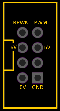
Pin compatible to IBT-2 Motor Driver.
| 6 | 5 | 4 | 3 | 2 | 1 |
|---|---|---|---|---|---|
| +5V | GND | n/c | CANL | CANH | n/c |
Use serial terminal to connect via USB (see above) to AstroCAN-AutoDome. If your browser supports “Web Serial”, you also can use the terminal available in the Firmware section. Communication speed ist 115200 baud. The following commands are available for configuration and management:
| Command | Parameters | Description | Example |
|---|---|---|---|
| /HELP | – | shows usage | /HELP |
| /SETTINGS | – | shows all settings stored in EEPROM | /SETTINGS |
| /WIFIAPSSID | AP SSID | sets the access point SSID | /WIFIAPSSID R2TOCH |
| /WIFIAPPASSWORD | AP Password | sets the access point password | /WIFIAPPASSWORD R2TOUCH123 |
| /WIFISSID | WIFI SSID | sets the WLAN SSID | /WIFISSID HOMELAN |
| /WIFIPASSWORD | WIFI Password | sets the WLAN Password | /WIFIPASSWORD HOMELAN123 |
| /PAIR | – | auto pair module with ESP-NOW peer (connect both modules to CAN for pairing)
Pairing mode depends on Dome jumper. When in dome mode, it looks for brain/shield module. When in body mode, it looks for bridge module. | /PAIR |
| /NOWLMK | 16 byte key | sets the local master key for ESP-NOW communication. See -> ESP-NOW encryption for details. | /NOWLMK 0123456789ABCDEF |
| /NOWPMK | 16 byte key | sets the primary master key for ESP-NOW communication. See -> ESP-NOW encryption for details. | /NOWPMK 0123456789ABCDEF |
| /NOWCHANNEL | Channel | sets the ESP-NOW channel number | /NOWCHANNEL 5 |
| /NOWSETPEER | MAC Address in xx:xx:xx:xx:xx:xx format | set ESP-NOW communication peer MAC address | /NOWSETPEER 01:23:45:67:89:AB |
| /NOWCLEARPEERS | – | clear all ESP-NOW communication peers | /NOWCLEARPEERS |
| /NOWLISTPEERS | – | list all ESP-NOW communication peers | /NOWLISTPEERS |
| /RESTART | – | restart module | /RESTART |
| /FACTORY | – | set factory settings and restart module. All EEPROM settings will also be set to default. | /FACTORY |
| /ACTIVATE | CAN|CAN1|CAN2|NOW|WIFI|ENC | acticate CAN-/NOW-/WIFI-Functionality or ESP-NOW encryption. CAN1/CAN2 only available on Dual-CAN-Boards. | /ACTIVATE CAN |
| /DEACTIVATE | CAN|CAN1|CAN2|NOW|WIFI|ENC | deacticate CAN-/NOW-/WIFI-Functionality or ESP-NOW encryption. CAN1/CAN2 only available on Dual-CAN-Boards. | /DEACTIVATE CAN |
| /NOWSETBRAIN | MAC Address in xx:xx:xx:xx:xx:xx format | set ESP-NOW brain/body peer address | /NOWSETBODY 01:23:45:67:89:AB |
| /SETMINSPEED | speed | set minimum dome rotation speed 0-100 (speed in percent) | /SETMINSPEED 50 |
| /SETINITSPEED | speed | set dome initialization rotation speed 0-100 (speed in percent) | /SETINITSPEED 70 |
| /SETAUTOINIT | [0|1] | dome autoinit at startup 0=no / 1=yes | /SETAUTOINIT 1 |
| /CALIBRATE | [ALL|SPEED|STEPS] | start calibration test(s): ALL – minimal speed + steps per 360 deg SPEED – minimal speed test only STEPS – steps per 360 deg only | /CALIBRATE ALL |
| /INITDOME | – | initialize dome position and turn to start position | /INITDOME |
| /ROTATE | speed | rotate dome motor at speed -100 to 100 (speed in percent). 0 to stop. | /ROTATE -50 |
| /TURN | degrees + speed | turn dome motor by degrees at speed 0 to 100 (speed in percent). | /TURN 45 100 |
| /POSITION | degrees + speed | move dome motor to absolute position degrees (0-365) at speed -100 to 100 (speed in percent). | /POSITION 180 -100 |
| /SPOSITION | degrees + speed | move dome motor to absolute position degrees (0-365) at speed 0 to 100 (speed in percent), shortest way. | /POSITION 270 50 |
| /SETP | double | set P value for PID tuning | /SETP 0.3 |
| /SETI | double | set I value for PID tuning | /SETI 0.0 |
| /SETD | double | set D value for PID tuning | /SETD 0.0 |
| /SETFRONT | – | stores the current position as front looking position | /SETFRONT |
| /SETAUTOMOVE | [0|1] | random dome movement | /SETAUTOMOVE 1 |
| /SETAUTOMAXDEG | degrees | random dome movement, max degrees | /SETAUTOMAXDEG 90 |
| /SETAUTOMINDEG | degrees | random dome movement, min degrees | /SETAUTOMINDEG -90 |
| /SETAUTOMAXSPEED | speed | random dome movement, max speed | /SETAUTOMAXSPEED 80 |
| /SETAUTOMINSPEED | speed | random dome movement, min speed | /SETAUTOMINSPEED 35 |
| /SETAUTOMAXTIME | milliseconds | random dome movement, max time between movements | /SETAUTOMAXTIME 12000 |
| /SETAUTOMINTIME | milliseconds | random dome movement, min time between movements | /SETAUTOMINTIME 4000 |
Use serial terminal to connect via USB (see above) to AstroCAN-Bridge. Communication speed ist 115200 baud. The following settings can be configured (see command set above):
| Setting | Description | Example | Config Command |
|---|---|---|---|
| MAC | MAC Address of ESP32 | 12:34:56:78:9A:BC | fix, not configurable |
| AP_SSID | Name of the access point network, the AstroCAN module opens up to get connected by apps like R2-Touch | R2TOUCH | /WIFIAPSSID |
| AP_Password | Password of the Access point network. | R2TOUCH123 | /WIFIAPPASSWORD |
| WLAN_SSID | Name of the WLAN the AstroCAN module can connect to, to be controlled by other systems within that network | HOMELAN | /WIFISSID |
| WLAN_Password | Password of the WLAN the AstroCAN module can connect to. | HOMELAN123 | /WIFIPASSWORD |
| NOW_PMK | ESP-NOW encryption parameter: Primary Master Key. See -> ESP-NOW encryption for details.
Only change, if you exactly know, what you are doing! | 0123456789ABCDEF | /NOWPMK |
| NOW_LMK | ESP-NOW encryption parameter: Local Master Key. See -> ESP-NOW encryption for details.
Only change, if you exactly know, what you are doing! | 0123456789ABCDEF | /NOWLMK |
| NOW_Channel | WIFI channel to be used for ESP-NOW communication. All ESP-NOW peers have to communicate over the same channel number | 5 | /NOWCHANNEL |
| CAN1_Active | Shows, if main CAN bus is active | true – activated false – deactivated | /ACTIVATE CAN /ACTIVATE CAN1 /DEACTIVATE CAN |
| CAN2_Active | Shows, if secondary CAN bus is active | true – activated false – deactivated | /ACTIVATE CAN2 /DEACTIVATE CAN2 |
| NOW_Active | Shows, if ESP-NOW is active | true – activated false – deactivated | /ACTIVATE NOW /DEACTIVATE NOW |
| WIFI_Active | Shows, if WIFI is active | true – activated false – deactivated | /ACTIVATE WIFI /DEACTIVATE WIFI or WIFI jumper |
| NOW_Encryption | Shows, if ESP-NOW encryption is active. See -> ESP-NOW encryption for details. | true – activated false – deactivated | /ACTIVATE ENC /DEACTIVATE ENC |
| MinSpeed | Minimum dome rotation speed (0-100), speed in percent | 35 | /SETMINSPEED |
| InitSpeed | Dome initialization rotation speed (0-100), speed in percent | 50 | /SETINITSPEED |
| SpeedFactor | Calibration factor for dome rotation direction. Calibrated automatically. | 1 | – |
| MotorRange | Number of steps for a 360 deg turn, center sensor not active. Calibrated automatically. | 1800 | – |
| CenterRange | Number of steps for a 360 deg turn, center sensor active. Calibrated automatically. | 30 | – |
| POS_Front | Front looking position | 300 | /SETFRONT |
| AutoInit | Dome autoinit at startup, 0=no / 1=yes | 0 | /SETAUTOINIT |
| PID_P | P value for PID tuning | 0.300000 | /SETP |
| PID_I | I value for PID tuning | 0.000000 | /SETI |
| PID_D | D value for PID tuning | 0.000000 | /SETD |
| Peers | Description | Example | Configuration |
| Peer | MAC-Adress of ESP-NOW communication partner, not used in autodome module | 12:34:56:78:9A:BC | /NOWSETPEER |
| Brain/Body | MAC-Adress of ESP-NOW communication partner placed in body | 12:34:56:78:9A:BC | /NOWSETBRAIN |
| AutoMove | random dome movement | true | /SETAUTOMOVE |
| AM_MaxDeg | random dome movement, max degrees | 90 | /SETAUTOMAXDEG |
| AM_MinDeg | random dome movement, min degrees | -90 | /SETAUTOMINDEG |
| AM_MaxSpeed | random dome movement, max speed | 80 | /SETAUTOMAXSPEED |
| AM_MinSpeed | random dome movement, min speed | 35 | /SETAUTOMINSPEED |
| AM_MaxTime | random dome movement, max time between movements, in ms | 12000 | /SETAUTOMAXTIME |
| AM_MinTime | random dome movement, min time between movements, in ms | 4000 | /SETAUTOMINTIME |
The AstroCan AutoDome provides precise dome positioning. Optionally it replaces the Syren10 motor controller by a simple H-Bridge motor controller like the BTS7960. If you already own the Syren10, it can be used in place of the BTS7960. See wiring examples for details.
All modules adhere to a standardized size and possess an identical “Astrobus” interface. This uniformity enables secure mounting onto the electronics board without the need for extensive wiring. However, the use of the Astrobus is not mandatory, and traditional free-floating wiring can be used if preferred.
To install most recent firmware V2.5.6 connect the AstroCAN module via USB to your computer and click on “Connect” button.
Attention 1: When upgrading one module to V2.x, you have to upgrade ALL other AstroCAN-Modules to V2.x!
Attention 2: Read HowTo – Upgrade to V2.5 before upgrading!
The firmware has been compiled using esptool, ready to flash to offset 0x00.
Firmware AstroCAN-AutoDome download
Read HowTo – Upgrade to V2.5 before upgrading!
Bugfixes
Features
Attention: When upgrading one module to V2.x, you have to upgrade ALL other AstroCAN-Modules to V2.x!
Bugfixes
Features
Attention: When upgrading one module to V2.x, you have to upgrade ALL other AstroCAN-Modules to V2.x!
Bugfixes
Features
Bugfixes
Features