AstroCAN Dual Mega Shield Pro
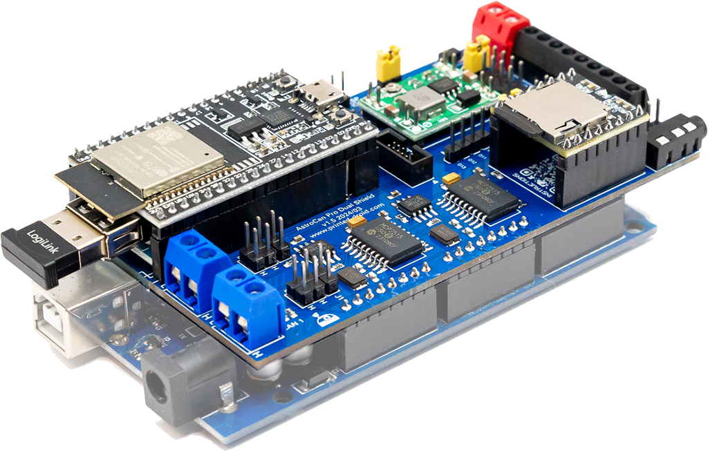

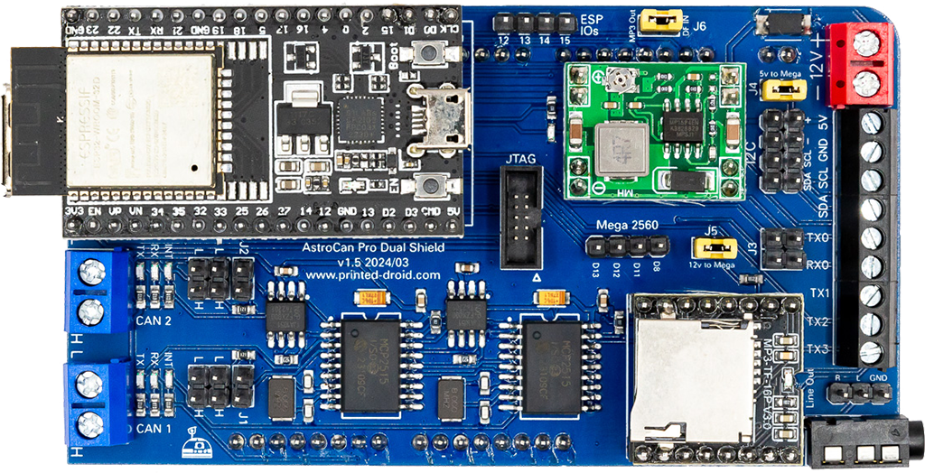
CAN-Bus #1 Screw Terminal. Same as CAN-Bus #1 Pin Header.
CAN-Bus #2 Screw Terminal. Same as CAN-Bus #2 Pin Header.
CAN-Bus #1 Pin Header.
CAN-Bus #2 Pin Header.
CAN-Bus #1 Terminator
CAN-Bus #2 Terminator
MP3-Player. Place SD-Card with Astromech-Sounds.
Stereo audio jack. Connect to your amplifier.
Audio Signal Pin-Header
Connections to Dome-Controller, Motor Controllers and Body-Controllers.
I2C bus screw connector. Used to connect additional modules.
I2C pin header. Used to connect additional modules.
Important: 7-12V ONLY! Otherwise you will damage your board.
Jumper to provide 5V power from Shield to ATMega. Recommended to leave open!
Jumper to provide power from Shield to ATMega. Don’t use separate power supply at ATMega board, then!
reserved for future use
12V to 5V step down module.
Closed: Use onboard DF-Mini-Player
Opened: fork communication to external sound modul
reserved for future use
Developers only
Press to restart module
Connector for flashing and configuring your device.
Hold for 3s to start ESP-Now-Pairing (see documentation for details)
Do not cover with metallic case etc.
Insert your Bluetooth-Token here
ESP32 Dev Kit V4
| Hotspot | Function | Description |
|---|---|---|
| 1 | CAN-Bus #1 | CAN-Bus #1 Screw Terminal. Same as CAN-Bus Pin Header |
| 2 | CAN-Bus #2 | CAN-Bus #2 Screw Terminal. Same as CAN-Bus Pin Header |
| 3 | CAN-Bus #1 | CAN-Bus #1 Pin Header |
| 4 | CAN-Bus #2 | CAN-Bus #2 Pin Header |
| 5 | CAN-Bus #1 Terminator | CAN-Bus #1 Terminator. See CAN Termination for details. |
| 6 | CAN-Bus #2 Terminator | CAN-Bus #2 Terminator. See CAN Termination for details. |
| 7 | DF-Mini MP3-Player | MP3-Player. Place SD-Card with Astromech-Sounds. |
| 8 | Audio Jack | Stereo audio jack. Connect to your amplifier. |
| 9 | Audio Signal | Audio Signal Pin-Header |
| 10 | Serial Screw Connectors | TX1: Connection to Dome-Controller TX2: Connection to Motor Controllers TX3: Connection to Body-Controller |
| 11 | I2C Connector Screw Connector | I2C Port for connecting other dome modules. |
| 12 | I2C Connector Pin Header | I2C Port for connecting other dome modules. |
| 13 | Power Supply, 12.0V | Power Supply, 12.0V. Important: 7-12V ONLY! Otherwise you will damage your board. |
| 14 | 5V Power Supply for ATMega | Jumper to provide 5V power from Shield to ATMega. Recommended to leave open! |
| 15 | ||
| 16 | 12V Power Supply for ATMega (recommended) | Jumper to provide power from Shield to ATMega. Don’t use separate power supply at ATMega board, then! |
| 17 | Free ATMega GPIOs | reserved for future use |
| 18 | Power Converter | 12V to 5V step down module. |
| 19 | MP3-Connector | Closed: Use onboard DF-Mini-Player
Opened: fork communication to external sound modul |
| 20 | Free ATMega GPIOs | reserved for future use |
| 21 | JTAG-Connector | Debugging Interface, Developers only |
| 22 | Reset Button | Press to restart module |
| 23 | USB-Connector | Connector for flashing and configuring your device |
| 24 | Pair / Boot Button | Hold for 3s to start ESP-Now-Pairing. Bridge module has to be connected to AstroCAN Shield / AstroCAN Brain via CAN-Bus to get paring information! |
| 25 | WIFI/NOW-Antenna | Do not cover with metallic case etc. |
| 26 | USB-Host-Connector (below antenna) | Insert your Bluetooth-Token here |
| 27 | ESP32 Dev Kit V4 | ESP32 Dev Kit V4 (in case you have to replace it…) |
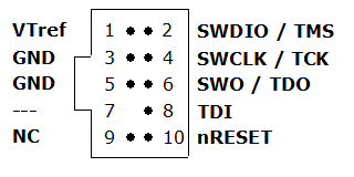
Use serial terminal to connect via USB (see above) to AstroCAN Module. If your browser supports “Web Serial”, you also can use the terminal available in the Firmware section. Communication speed ist 115200 baud. The following commands are available for configuration and management:
| Command | Parameters | Description | Example |
|---|---|---|---|
| /HELP | – | shows usage | /HELP |
| /SETTINGS | – | shows all settings stored in EEPROM | /SETTINGS |
| /WIFIAPSSID | AP SSID | sets the access point SSID | /WIFIAPSSID R2TOCH |
| /WIFIAPPASSWORD | AP Password | sets the access point password | /WIFIAPPASSWORD R2TOUCH123 |
| /WIFISSID | WIFI SSID | sets the WLAN SSID | /WIFISSID HOMELAN |
| /WIFIPASSWORD | WIFI Password | sets the WLAN Password | //WIFIPASSWORD HOMELAN123 |
| /PAIR | – | auto pair module with ESP-NOW peer (connect both modules to CAN for pairing)
Pairing mode depends on Dome jumper. When in dome mode, it looks for brain/shield module. When in body mode, it looks for bridge module. | /PAIR |
| /NOWLMK | 16 byte key | sets the local master key for ESP-NOW communication. See -> ESP-NOW encryption for details. | /NOWLMK 0123456789ABCDEF |
| /NOWPMK | 16 byte key | sets the primary master key for ESP-NOW communication. See -> ESP-NOW encryption for details. | /NOWPMK 0123456789ABCDEF |
| /NOWCHANNEL | Channel | sets the ESP-NOW channel number | /NOWCHANNEL 5 |
| /NOWSETPEER | MAC Address in xx:xx:xx:xx:xx:xx format | set ESP-NOW communication peer MAC address | /NOWSETPEER 01:23:45:67:89:AB |
| /NOWCLEARPEERS | – | clear all ESP-NOW communication peers | /NOWCLEARPEERS |
| /NOWLISTPEERS | – | list all ESP-NOW communication peers | /NOWLISTPEERS |
| /RESTART | – | restart module | /RESTART |
| /FACTORY | – | set factory settings and restart module. All EEPROM settings will also be set to default. | /FACTORY |
| /ACTIVATE | CAN|CAN1|CAN2|NOW|WIFI|ENC | acticate CAN-/NOW-/WIFI-Functionality or ESP-NOW encryption. CAN1/CAN2 only available on Dual-CAN-Boards. | /ACTIVATE CAN |
| /DEACTIVATE | CAN|CAN1|CAN2|NOW|WIFI|ENC | deacticate CAN-/NOW-/WIFI-Functionality or ESP-NOW encryption. CAN1/CAN2 only available on Dual-CAN-Boards. | /DEACTIVATE CAN |
| /NOWSETDOME | MAC Address in xx:xx:xx:xx:xx:xx format | set ESP-NOW dome peer address (used, if bridge is in body mode) | /NOWSETDOME 01:23:45:67:89:AB |
| /SETSOUND | MP3|DFM|HCR | set sound module for testing purpose MP3 – SparkFun MP3 trigger DFM – DF Mini Player HCR – Astromech Vocalizer | /SETSOUND DFM |
| /PLAY | 0..255 | Plays a sound from the SD card | /PLAY 255 |
Use serial terminal to connect via USB (see above) to AstroCAN-Module. Communication speed ist 115200 baud. The following settings can be configured (see command set above):
| Setting | Description | Example | Config Command |
|---|---|---|---|
| MAC | MAC Address of ESP32 | 12:34:56:78:9A:BC | fix, not configurable |
| AP_SSID | Name of the access point network, the AstroCAN module opens up to get connected by apps like R2-Touch | R2TOUCH | /WIFIAPSSID |
| AP_Password | Password of the Access point network. | R2TOUCH123 | /WIFIAPPASSWORD |
| WLAN_SSID | Name of the WLAN the AstroCAN module can connect to, to be controlled by other systems within that network | HOMELAN | /WIFISSID |
| WLAN_Password | Password of the WLAN the AstroCAN module can connect to. | HOMELAN123 | /WIFIPASSWORD |
| NOW_PMK | ESP-NOW encryption parameter: Primary Master Key. See -> ESP-NOW encryption for details.
Only change, if you exactly know, what you are doing! | 0123456789ABCDEF | /NOWPMK |
| NOW_LMK | ESP-NOW encryption parameter: Local Master Key. See -> ESP-NOW encryption for details.
Only change, if you exactly know, what you are doing! | 0123456789ABCDEF | /NOWLMK |
| NOW_Channel | WIFI channel to be used for ESP-NOW communication. All ESP-NOW peers have to communicate over the same channel number | 5 | /NOWCHANNEL |
| CAN1_Active | Shows, if main CAN bus is active | true – activated false – deactivated | /ACTIVATE CAN /ACTIVATE CAN1 /DEACTIVATE CAN |
| CAN2_Active | Shows, if secondary CAN bus is active | true – activated false – deactivated | /ACTIVATE CAN2 /DEACTIVATE CAN2 |
| NOW_Active | Shows, if ESP-NOW is active | true – activated false – deactivated | /ACTIVATE NOW /DEACTIVATE NOW |
| WIFI_Active | Shows, if WIFI is active | true – activated false – deactivated | /ACTIVATE WIFI /DEACTIVATE WIFI or WIFI jumper |
| NOW_Encryption | Shows, if ESP-NOW encryption is active. See -> ESP-NOW encryption for details. | true – activated false – deactivated | /ACTIVATE ENC /DEACTIVATE ENC |
| PLAYER | Configured Sound Player | MP3 – Sparkfun MP3 Trigger DFM – DF Robot Mini Player HCR – Astromech Vocalizer | /SETSOUND |
| Peers | Description | Example | Configuration |
| Peer | MAC-Adress of ESP-NOW communication partner, not used in bridge module | 12:34:56:78:9A:BC | /NOWSETPEER |
| Dome | MAC-Adress of ESP-NOW communication partner place in dome | 12:34:56:78:9A:BC | /NOWSETDOME |
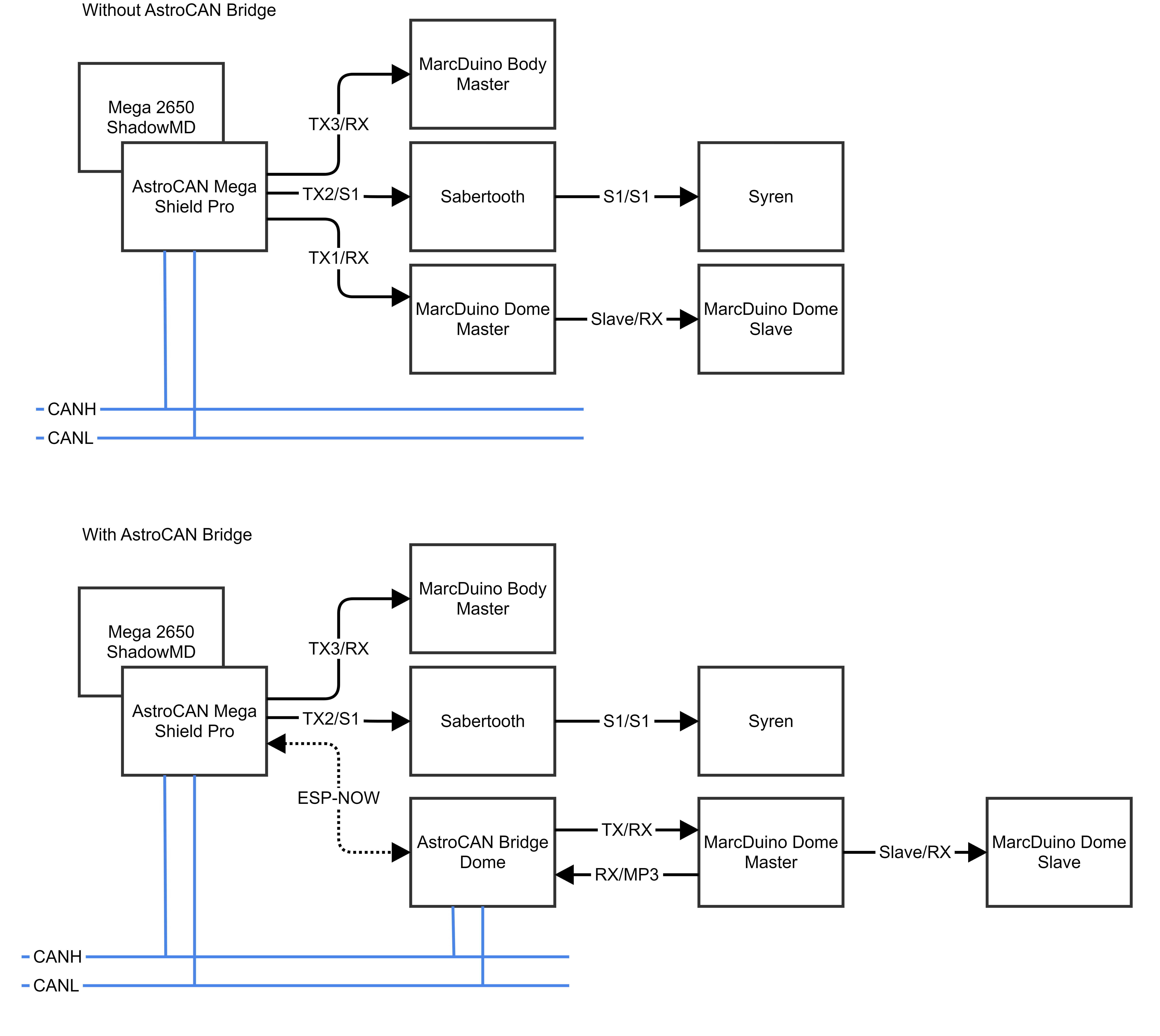
The AstroCan Pro Dual Shield can easily be added to existing Shadow MD systems without any additional system adjustments, including software modifications. It serves as the initial entry point into the Astro CAN world and aims to replace the flawed Host-Shield-2.0 models available in the market. This shield combines the capabilities of the CAN bus and the USB mini host shield. For individuals experienced in CAN, the dual-CAN feature allows for the establishment of two separate bus systems with varying speeds to handle different tasks, such as integrating high-speed sensors with either 500kbps or 1Mbps. Additionally, it may also support future CAN-Bus motor controls.
No. The USB-Host integrated in the AstroCAN-Shield is tested and working 100%. A standard ATMega 2560 board is fine.
To install most recent firmware V2.5.6 connect the AstroCAN module via USB to your computer and click on “Connect” button.
Attention 1: When upgrading one module to V2.x, you have to upgrade ALL other AstroCAN-Modules to V2.x!
Attention 2: Read HowTo – Upgrade to V2.5 before upgrading!
The firmware has been compiled using esptool, ready to flash to offset 0x00.
Firmware AstroCAN-MegaShield download
Read HowTo – Upgrade to V2.5 before upgrading!
Bugfixes
Features
Attention: When upgrading one module to V2.x, you have to upgrade ALL other AstroCAN-Modules to V2.x!
Bugfixes
Features
Attention: When upgrading one module to V2.x, you have to upgrade ALL other AstroCAN-Modules to V2.x!
Bugfixes
Features
Bugfixes