Components
| DPL | Data Port Logics |
| (D)CBI | Charge Bay Indicator |
| CSI | Coin Slot Indicator |
| LDPL | Large Data Port Logics |
| VU | Volume Unit |
| UAL | Utility Arms Logics |
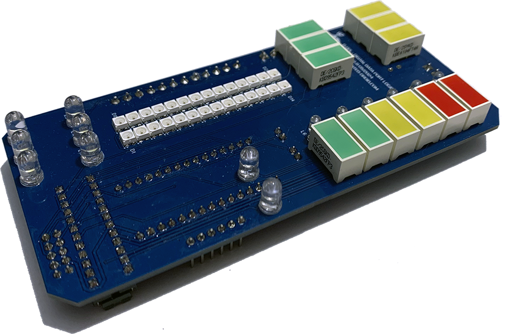
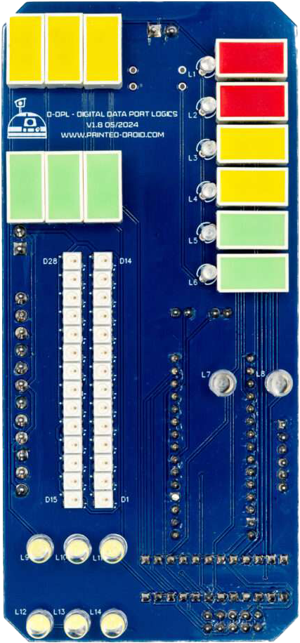
DPL+VU (analog + digital VU)
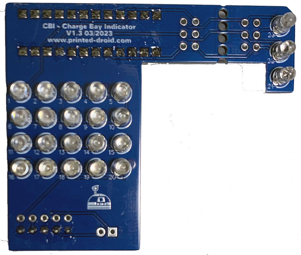
CBI (analog)
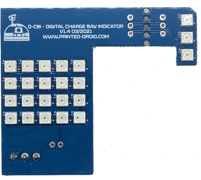
D-CBI (digital)
LDPL
UAL
Connectors
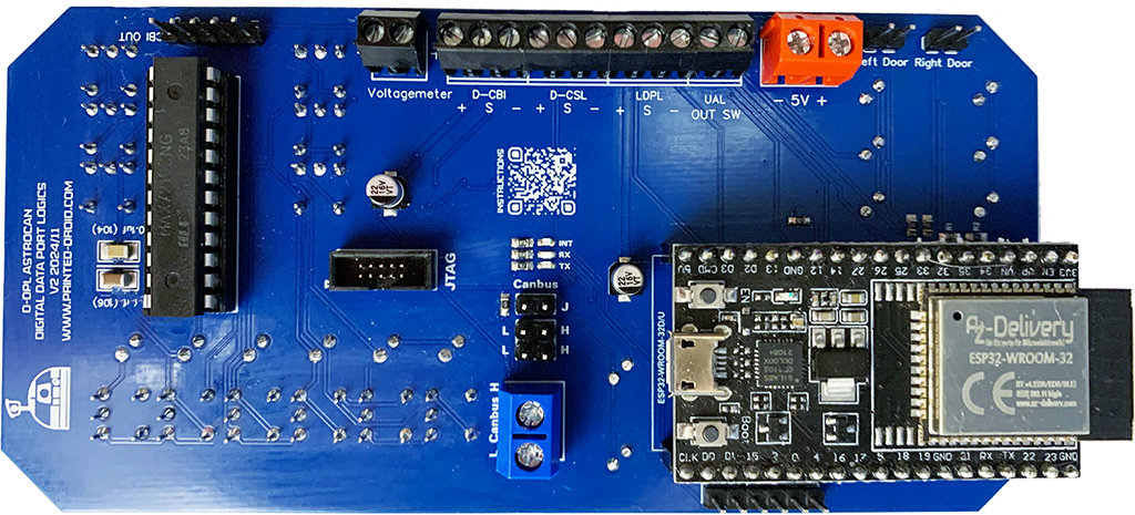
CAN-Bus
Can-Bus Screw Terminal. Same as CAN-Bus Pin Header.
Power Supply
Important: 5V ONLY! Otherwise you will damage your board.
!Check polarity!
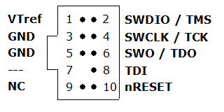
JTAG-Connector
Debugging Interface, Developers only.
I2C Connector
I2C Port for connecting other dome modules.
ESP32 Dev Kit V4
ESP32 Dev Kit V4
WIFI/NOW-Antenna
Do not cover with metallic case etc.
CAN-Bus
Can-Bus pin header
CAN-Bus Terminator
CAN-Bus Terminator
Reset Button
Press to restart module
USB-Connector
Connector for flashing and configuring your device.
Pair / Boot Button
Hold for 3s to start ESP-Now-Pairing (see documentation for details)
Voltage Connector
Connector for Battery Voltage
CBI (digital) Connector
Connector for digital CBI module. + = VCC, S = Signal, – = GND
CSL (digital) Connector
Connector for digital CSL module. + = VCC, S = Signal, – = GND
LDPL (digital) Connector
Connector for digital LDPL module. + = VCC, S = Signal, – = GND
UAL (digital) Connector
Connector for digital UAL module. OUT = Signal, SW = UAL Switch
Left Door Switch Connector
Connector DPL door. LOW when open.
Right Door Switch Connector
Connector CBI door. LOW when open.
CBI (analog) Connector
Connector for analog CBI
| Hotspot | Function | Description |
|---|---|---|
| 1 | CAN-Bus | CAN-Bus Pin Header |
| 2 | Power Supply, 5.0V | Power Supply, 5.0V. Important: 5V ONLY! Otherwise you will damage your board. |
| 3 | JTAG-Connector | Debugging Interface, Developers only |
| 4 | I2C Connector | I2C Port for connecting other dome modules. |
| 5 | ESP32 Dev Kit V4 | ESP32 Dev Kit V4 (in case you have to replace it…) |
| 6 | WIFI/NOW-Antenna | Do not cover with metallic case etc. |
| 7 | CAN-Bus | Can-Bus Screw Terminal. Same as CAN-Bus Pin Header |
| 8 | CAN-Bus Terminator | CAN-Bus Terminator. See CAN Termination for Details |
| 8 | Reset Button | Press to restart module |
| 10 | USB-Connector | Connector for flashing and configuring your device |
| 11 | Pair / Boot Button | Hold for 3s to start ESP-Now-Pairing. Bridge module has to be connected to AstroCAN Shield / AstroCAN Brain via CAN-Bus to get paring information! |
| 12 | Voltage Meter | Connector for Battery Voltage. Important: Check for correct resistors matching your maximum battery/charging voltage, otherwise you will destroy your board |
| 13 | CBI (digital) Connector | Connector for your digital CBI module + = VCC S = Signal/Data – = GND |
| 14 | CSL (digital) Connector | Connector for your digital CSL module + = VCC S = Signal/Data – = GND |
| 15 | LDPL (digital) Connector | Connector for your digital LDPL module + = VCC S = Signal/Data – = GND |
| 16 | UAL (digital) Connector | Connector for your digital UAL module OUT = Signal/Data SW = UAL-Switch (Low Active |
| 17 | Left Door (DPL) Switch Connector | Connector for DPL-Door. LOW = Door Open |
| 18 | Right Door (CBI) Switch Connector | Connector for CBI-Door. LOW = Door Open |
| 19 | CBI (analog) Connector | Connector for your analog CBI module |
JTAG
Light Configuration Commands
Use serial terminal to connect via USB (see above) to AstroCAN-Module. If your browser supports “Web Serial”, you also can use the terminal available in the Firmware section. Communication speed ist 115200 baud. The following commands are available for configuration and management.
Note: The light configuration parameters differ from the common AstroCAN syntax. This is due to compatibility to the Arduino Nano board with less memory.
Light Configuration Command Structure
/_module_/_param_/_value1_/_value2_/_value…_
Modules
DP – DLP
CB – CBI
DC – D-CBI
CS – CSL
LD – LDPL
VU – VUBar
UA – UAL
Optional additional moduls (available in some special releases)
TB – Top Block (= Yellow and Green Block together)
YB – Yellow Block
GB – Green Block
BL – Blue Lights
BG – BarGraph
RL – Red Lights
WL – White Lights
Parameters
CO – Base Color, 3 separate Values for R/G/B, 0-255 each
BR – Brightness, 1 Value 0-255
AN – Animation Number, 1 Value 0-255
AS – Animation Speed, 1 Value 0 – 65535
EF – Effect, 1 Value 0-255
ES – Effect Speed, 1 Value 0-65535
VM – Voltage Monitor, 1 Value 0/1
VL – Voltage Limits, 4 Values (red, yellow, green, charge)
RR – Resistor Values, 2 Values R1 + R2
Examples
/DP/BR/15 – DPL, Brightness 15 (0-15 for analog modules)
/LD/BR/50 – LDPL, Brightness 50 (0-255 for AstroPixels)
/CS/CO/255/0/0 – CSI, Base Color Red (R/G/B)
/DP/RR/10000.0/1000.0 – R1 = 10K, R2 = 1K
/DP/VL/11.5/12.0/12.5/13.0 – red = 11.5V, yellow = 12.0V, green = 12.5V, charge = 13.0V
:
AstroCAN Commands
| Command | Parameters | Description | Example |
|---|---|---|---|
| /HELP | – | shows usage | /HELP |
| /SETTINGS | – | shows all settings stored in EEPROM | /SETTINGS |
| /WIFIAPSSID | AP SSID | sets the access point SSID | /WIFIAPSSID R2TOCH |
| /WIFIAPPASSWORD | AP Password | sets the access point password | /WIFIAPPASSWORD R2TOUCH123 |
| /WIFISSID | WIFI SSID | sets the WLAN SSID | /WIFISSID HOMELAN |
| /WIFIPASSWORD | WIFI Password | sets the WLAN Password | /WIFIPASSWORD HOMELAN123 |
| /PAIR | – | auto pair module with ESP-NOW peer (connect both modules to CAN for pairing)
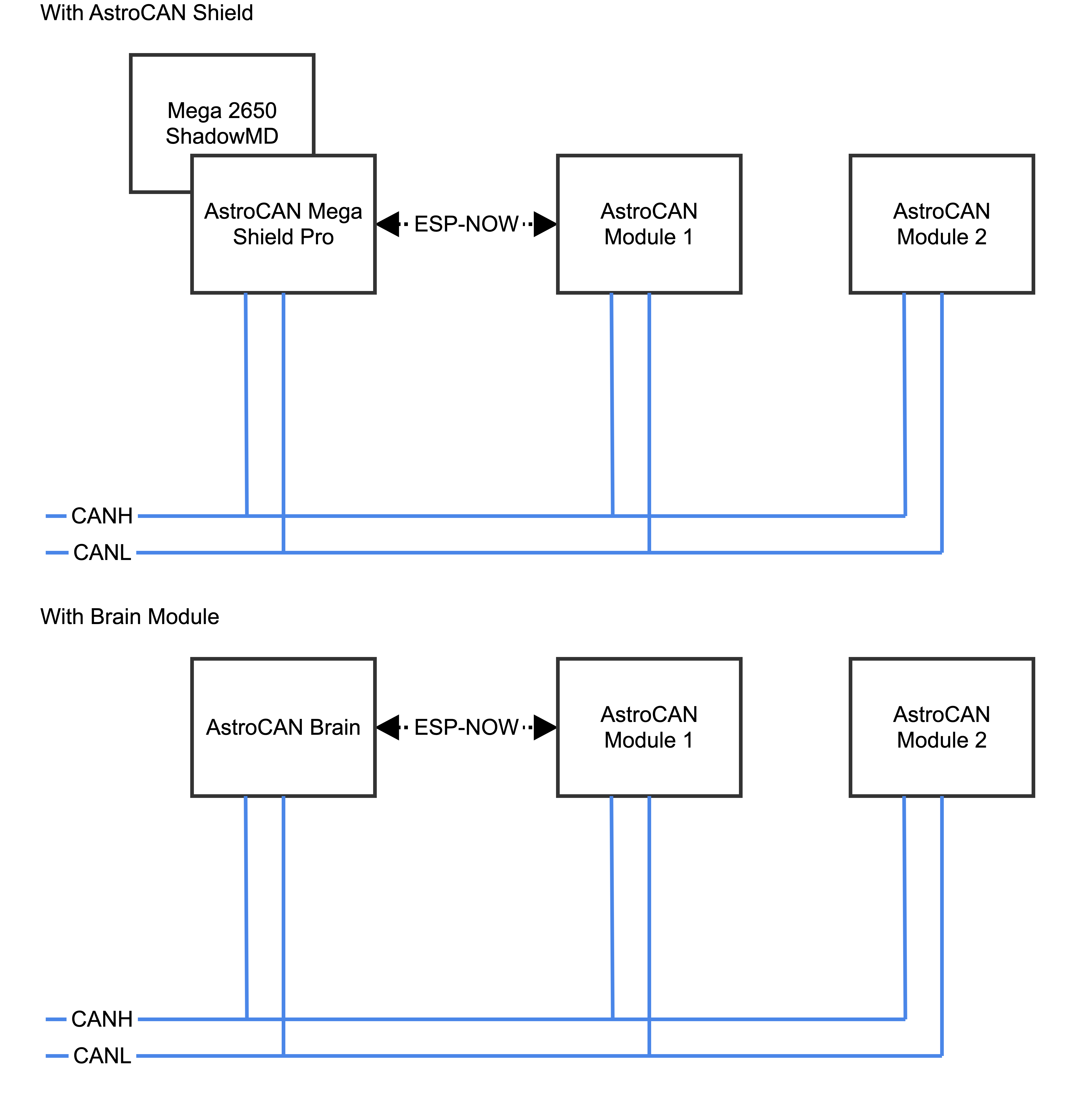
Pairing mode depends on Dome jumper. When in dome mode, it looks for brain/shield module. When in body mode, it looks for bridge module. | /PAIR |
| /NOWLMK | 16 byte key | sets the local master key for ESP-NOW communication. See -> ESP-NOW encryption for details. | /NOWLMK 0123456789ABCDEF |
| /NOWPMK | 16 byte key | sets the primary master key for ESP-NOW communication. See -> ESP-NOW encryption for details. | /NOWPMK 0123456789ABCDEF |
| /NOWCHANNEL | Channel | sets the ESP-NOW channel number | /NOWCHANNEL 5 |
| /NOWSETPEER | MAC Address in xx:xx:xx:xx:xx:xx format | set ESP-NOW communication peer MAC address | /NOWSETPEER 01:23:45:67:89:AB |
| /NOWCLEARPEERS | – | clear all ESP-NOW communication peers | /NOWCLEARPEERS |
| /NOWLISTPEERS | – | list all ESP-NOW communication peers | /NOWLISTPEERS |
| /RESTART | – | restart module | /RESTART |
| /FACTORY | – | set factory settings and restart module. All EEPROM settings will also be set to default. | /FACTORY |
| /ACTIVATE | CAN|CAN1|CAN2|NOW|WIFI|ENC | acticate CAN-/NOW-/WIFI-Functionality or ESP-NOW encryption. CAN1/CAN2 only available on Dual-CAN-Boards. | /ACTIVATE CAN |
| /DEACTIVATE | CAN|CAN1|CAN2|NOW|WIFI|ENC | deacticate CAN-/NOW-/WIFI-Functionality or ESP-NOW encryption. CAN1/CAN2 only available on Dual-CAN-Boards. | /DEACTIVATE CAN |
| /NOWSETBRAIN | MAC Address in xx:xx:xx:xx:xx:xx format | set ESP-NOW brain/body peer address | /NOWSETBRAIN 01:23:45:67:89:AB |
| Light Modules Commands as described above |
Settings
Use serial terminal to connect via USB (see above) to AstroCAN-Bridge. Communication speed ist 115200 baud. The following settings can be configured (see command set above):
| Setting | Description | Example | Config Command |
|---|---|---|---|
| MAC | MAC Address of ESP32 | 12:34:56:78:9A:BC | fix, not configurable |
| AP_SSID | Name of the access point network, the AstroCAN module opens up to get connected by apps like R2-Touch | R2TOUCH | /WIFIAPSSID |
| AP_Password | Password of the Access point network. | R2TOUCH123 | /WIFIAPPASSWORD |
| WLAN_SSID | Name of the WLAN the AstroCAN module can connect to, to be controlled by other systems within that network | HOMELAN | /WIFISSID |
| WLAN_Password | Password of the WLAN the AstroCAN module can connect to. | HOMELAN123 | /WIFIPASSWORD |
| NOW_PMK | ESP-NOW encryption parameter: Primary Master Key. See -> ESP-NOW encryption for details.
Only change, if you exactly know, what you are doing! | 0123456789ABCDEF | /NOWPMK |
| NOW_LMK | ESP-NOW encryption parameter: Local Master Key. See -> ESP-NOW encryption for details.
Only change, if you exactly know, what you are doing! | 0123456789ABCDEF | /NOWLMK |
| NOW_Channel | WIFI channel to be used for ESP-NOW communication. All ESP-NOW peers have to communicate over the same channel number | 5 | /NOWCHANNEL |
| CAN1_Active | Shows, if main CAN bus is active | true – activated false – deactivated | /ACTIVATE CAN /ACTIVATE CAN1 /DEACTIVATE CAN |
| CAN2_Active | Shows, if secondary CAN bus is active | true – activated false – deactivated | /ACTIVATE CAN2 /DEACTIVATE CAN2 |
| NOW_Active | Shows, if ESP-NOW is active | true – activated false – deactivated | /ACTIVATE NOW /DEACTIVATE NOW |
| WIFI_Active | Shows, if WIFI is active | true – activated false – deactivated | /ACTIVATE WIFI /DEACTIVATE WIFI or WIFI jumper |
| NOW_Encryption | Shows, if ESP-NOW encryption is active. See -> ESP-NOW encryption for details. | true – activated false – deactivated | /ACTIVATE ENC /DEACTIVATE ENC |
| Light Modules Settings as described above | |||
| Peers | Description | Example | Configuration |
| Peer | MAC-Adress of ESP-NOW communication partner, not used in autodome module | 12:34:56:78:9A:BC | /NOWSETPEER |
| Brain/Body | MAC-Adress of ESP-NOW communication partner placed in body | 12:34:56:78:9A:BC | /NOWSETBRAIN |
F.A.Q – AstroCAN Dome Lights
What is it?
The AstroCAN Body Lights / Digital Data Port Logics VU is an enhanced version of the original DPL for Astromechs.
The main difference to the classic DPL are the additional digital RGB LEDs and supports digital CBI, CSL, LDPL and UAL modules. Analog CBI modules are supported as well.
With coding you can show battery status via the digital LEDs, use it as a VU meter or whatever your creativity tells you.
Features
- AstroCAN extension module
- ESP-NOW Wireless Comm (Serial, CAN-Bus, I2C)
- JTAG-Live Debugging
- Status Leds for CanBus transmission
- Everything on 1 pcb – MicroController, terminals for power and voltage sensor are integrated in the DPL – even added I2C & serial breakout
- Digital VU Leds
- Terminals for the other Printed Droid Body Lights
- Better tracing
- Improved LED alignment
Best Practice – Wiring
Firmware Installer
To install most recent firmware V2.5.7 connect the AstroCAN module via USB to your computer and click on “Connect” button.
Attention 1: When upgrading one module to V2.x, you have to upgrade ALL other AstroCAN-Modules to V2.x!
Attention 2: Read HowTo – Upgrade to V2.5 before upgrading!
Firmware Download
ESP-Tool-Upgrade
The firmware has been compiled using esptool, ready to flash to offset 0x00.
Firmware AstroCAN-Bodylights download
OTA-Upgrade (Firmware 2.5 and greater)
Read HowTo – Upgrade to V2.5 before upgrading!
Revision History
Version 2.5.7 (16. September 2025)
Bugfixes
- Door status info missing
Features
- –
Attention: When upgrading one module to V2.x, you have to upgrade ALL other AstroCAN-Modules to V2.x!
Version 2.5.6 (15. September 2025)
Bugfixes
- –
Features
- All new upgrade including OTA update with WebServer
Attention: When upgrading one module to V2.x, you have to upgrade ALL other AstroCAN-Modules to V2.x!
Version 1.0.3 (8. January 2025)
Bugfixes
- –
Features
- First official release

